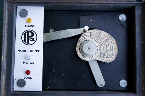
Very luckily I came into possession of a free electric kiln. It came with an old temperature control unit that I’ve decided to get back into working order so I can fire my own ceramics. The controller is made by the Industrial Pyrometer Company, which now seems to have become Mitsco. It uses a clever cam-follower system to regulate the kiln temperature and heating rate. The cam wheel has a scale laid out on it with the rings corresponding to 100C increases and the radial bands equaling 2 hour periods (a full rotation takes 24 hours). A sprung arm follows the edge of this cam around and through a system of gears, rotates a potentiometer inside the unit. An R-type thermocouple probe is used to monitor the temperature inside the kiln providing feedback to the control unit, which is compared to the cam-follower position using a simple Op Amp circuit (based on an F709PC chip). A relay is then triggered to turn the kiln on or off.
Today I’ve modified two of my servos to allow access to the output of the variable resistor inside them. This very simple modification opens up a world of possibilities that really should come as standard on all servos. All that’s involved is opening your servo, locating the potentiometer that provides feedback on where the output shaft is and then adding an extra wire onto the center tap. After adding this wire you can read the voltage present using an A/D converter and following some simple calibration, know quite precisely what angle the output shaft is at.
The actual modification is discussed in detail over at Trossen Robotics so I won’t go into that too much.
Here’s a video of what I cooked up using the newly modified servos and an arduino board.
You can see that as I twist the horn of one servo, the other rotates to match it and mirrors the movement very closely. To do this the value from the feedback pot is read using the analogRead() function. As the output of the feedback line only reaches around 2 Volts at maximum (and goes down to around 0.2V at the other end of travel) the AREF pin of the arduino must have a voltage just above this applied to get good A/D resolution.
To scale the A/D readings I connected a simple voltage divider between GND, +5V and the AREF pin. A note here is that when I measured the maximum output from the feedback pot without the servo being connected to the arduino I measured 1.2V for one and 1.3V for the other and made my divider to output around 1.37V. However, when I connected the ground from the servos to the ground of the arduino board, the voltage seen at the outputs moved closer to 2V, which messed up my readings and meant that the A/D converter was reporting a value of 1023 (max) at about a quarter of a rotation of the servo. This was down to the fact that I was using a separate power supply for the servos which was obviously mismatched slightly from the arduino board voltage. So make sure you hook everything together before you measure the servo voltage and work out which resistors to use in your divider. Incidentally, I used values of 5.1Kohms and 4.7Kohms, worked out using this calculator.
The code I used on the arduino was largely based around the example on the Trossen Robotics page. It’s available to download below.
I made this after becoming fascinated with the dry brushing technique used by modellers. Made using fimo, cling film (to mold the base of the original dock), a rock and knife for texturing and some old coins for a bit of weight.
My original idea was to have tiny N or HO scale people worshipping it, sort of like the 2001: A Space Odyssey Monolith. That never happened, as i was pretty happy with just the rock effect.
I needed a PIR sensor for a halloween project and not having a Maplin near by I decided to modify an £8.99 Security Floodlight from Argos. One thing you should note is that the default ‘switch-on’ time is around 1 minute. I didn’t need to change this for my application, but it may be an issue if you only need a short high-pulse when something is detected.
Ever Noticed that ‘Garlic’ and ‘Dalek’ sound the same? I have!. One is a close relation to an onion and official deodoriser of the French, the other is grotesque mutated organism integrated with a tank-like mechanical casing made of “dalekenium”. All these similarities (yes, all of them) got me thinking, maybe we could somehow fuse xenophobic killer mutants-in-a-box with dough and create…wait for it… Dalek Bread. Lets begin. Continue reading
BEAM robots are great. For those of you who don’t know what it is, check out the BEAM Wikipedia entry for a quick run down.
For a start, most BEAM robots can be assembled out of mostly junk parts. Even if you have to buy new parts, there is usually a very low component count for each robot, making each project cheap.
For this project I wanted to make a small flower that responded to light in some way, using only components that I already had to hand. This is what I came up with:
Components used were as follows:
Panasonic BP-242221 Solar Panel
Pager motor
0.047F 5.5V Capacitor
1x 1K Resistor
1x 100K Resistor
1x 220K Resistor
1N4148 Diode (or similar)
2x 2N3906 PNP Transistors
1x 2N3904 NPN Transistor
An empty beer can for the petals
The base of an old PP3 battery for the stand
The wheel of a small toy car used to mount the flower to the motor
Wire for connecting components
A glue gun & plenty of glue
When the flower is exposed to light the solar panel is charging the storage capacitor. As the light level drops off, the drop in charging current triggers the circuit and the energy stored in the capacitor is dumped into the pager motor, spinning the flower. In practice this means that when the sun is out the flower is charging, then as it is covered by clouds the charging current drops and the flower spins very rapidly.
Below is the schematic for the flower. It is based on the ‘Type 3 Solar Engine‘ design by Wilf Rigter. I didn’t have the same transistor to hand, but as with most things in the BEAM world, parts can be substituted for ones of a similar type with little effect on the final performance.
The components were free-formed using the ‘rat’s nest’ construction method. This doesn’t result in the cleanest finish (not in my hands anyway) but it does allow for a small form
A glue gun was used to secure the components and the bottom of an old PP3 type 9V battery was used as a support to keep the flower standing up
The flower was made out of an old beer can. Layers of petals were cut out in descending size and then stacked and hot-glued together.
This version was more of a quick prototype that a work of art, as you can tell.
I found that the wheel of a small toy car was a perfect fit onto the axle of the pager motor. This provided a nice flat surface to glue the flower too.