The box features a switch and a hinged lid. When someone presses the switch an arm inside lifts the lid, switches the switch back in the opposite direction and then closes again. Useless, but strangely compelling.
After seeing the original most useless machine ever I couldn’t resist making one myself, not for myself though, this one was a present. As the site hosting the original is horrible, I used the nice clear instructions provided by Make Projects.
I spent some time looking for a suitable box to house the machine’s useless innards, but finding one the right sort of size without any ugly decoration proved tricky, so I opted to make the box myself.
I have a Sony Vaio laptop (model VGN-C1Z), which all of a sudden developed a serious illness. The screen was covered in lines during bootup, both the BIOS and Windows loading screens, then it would just blackout when Windows finally loaded. The lines over the BIOS screen told me it was a graphics card problem and being a laptop I feared the worst. It turns out that I’m not the only one with this problem. The culprit here is the nVidia 7400 GPU. It seems that as the chip gets hot and cools down repeatedly, the solder bonds under the chip are weakened and eventually become faulty.
Now, it stands to reason that if the only error is poor solder connections, that I should be able to heat the chip up again and reflow the solder to create nice strong bonds again. Well to test my theory I booted the laptop, pressed F8 to get the windows boot menu and started in VGA mode. This let the laptop start Windows, albeit with everything looking huge due to the 800×600 resolution. Then I played helpful 720p videos until the laptop got very hot. A reboot later and the lines on the screen had disappeared! The laptop had magically resoldered itself. Sadly this didn’t last and the problem quickly returned.
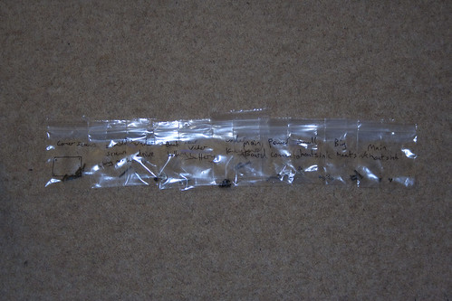
An easy way to keep track of the screws
I needed a more permanent fix, so I bought myself a heat gun and set about taking the laptop apart. Now a tip here is to get yourself a load of small plastic resealable bags. As I removed the screws I labelled a bag and put the screws in, so I might have a bag labelled ‘corner screws base’ with all the main screws from the base…obviously. Also, if you lay the bags out left to right in the order you took them out in, then you can easily follow the order in reverse to put everything back together.
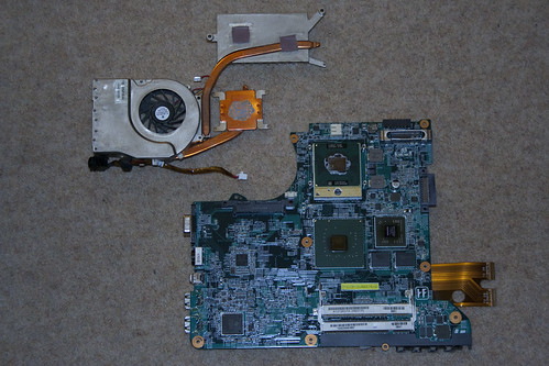
Heatsink and motherboard
After removing all the base screws, taking out the HDD/DVD drive (there are 3 screws under the drive), you have to flip it over and take off the keyboard, which is secured by small clips along the top edge and has a flat plastic ribbon on the back which has to be unplugged. There are 3 screws under the keyboard, which when removed will allow the laptop to come apart nicely. You can then unclip the wires from the motherboard, unscrew it and take it out. Then you remove the heatsink and finally the faulty nVidia GPU becomes visible.
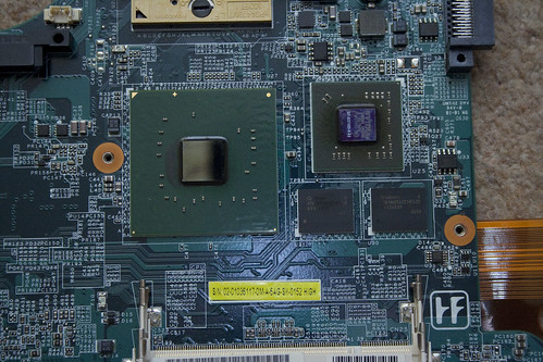
nVidia chip is the medium sized one on the right
I took a piece of tinfoil and rubbed it over the GPU to give me the outline. Then I cut out a section of foil inside the outline and covered the motherboard so that only the GPU was showing. I set my heat gun to 400C and holding approximately 15cm away to start with heated the nVidia chip. I did this for about a minute then let it cool down, before repeating the process again a couple of times, just to be sure. I then connected the bare minimum back up to the laptop to test it and SHAZAM! no lines on the screen. Job done. It was then a simple matter to take the screws out of their little labelled bags in reverse order and put the laptop back together. I’m still using the laptop with no problems since.
Update – 5th June 2011: Added some pictures I’d taken of the process to make things clearer.
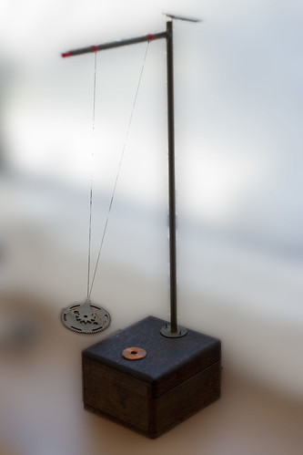
A little solar powered pendulum that I made a few years back. It uses a very simple circuit with just 2 transistors, a couple of resistors, a diode and some capacitors. Power is supplied by a two calculator solar panels wired in parallel for faster charging. The power is dumped into a coil which repels a magnet (disguised by some old brass gears) hanging from some fishing line. As the magnet swings back towards the coil the EMF generated lights a red LED in the top post and the power from the capacitors is dumped into the coil again giving the pendulum a little kick, forcing it higher.
Video, more pics and the schematic after the jump.
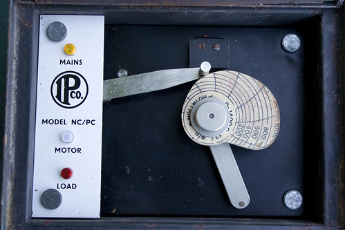
Very luckily I came into possession of a free electric kiln. It came with an old temperature control unit that I’ve decided to get back into working order so I can fire my own ceramics. The controller is made by the Industrial Pyrometer Company, which now seems to have become Mitsco. It uses a clever cam-follower system to regulate the kiln temperature and heating rate. The cam wheel has a scale laid out on it with the rings corresponding to 100C increases and the radial bands equaling 2 hour periods (a full rotation takes 24 hours). A sprung arm follows the edge of this cam around and through a system of gears, rotates a potentiometer inside the unit. An R-type thermocouple probe is used to monitor the temperature inside the kiln providing feedback to the control unit, which is compared to the cam-follower position using a simple Op Amp circuit (based on an F709PC chip). A relay is then triggered to turn the kiln on or off.
Today I’ve modified two of my servos to allow access to the output of the variable resistor inside them. This very simple modification opens up a world of possibilities that really should come as standard on all servos. All that’s involved is opening your servo, locating the potentiometer that provides feedback on where the output shaft is and then adding an extra wire onto the center tap. After adding this wire you can read the voltage present using an A/D converter and following some simple calibration, know quite precisely what angle the output shaft is at.
The actual modification is discussed in detail over at Trossen Robotics so I won’t go into that too much.
Here’s a video of what I cooked up using the newly modified servos and an arduino board.
You can see that as I twist the horn of one servo, the other rotates to match it and mirrors the movement very closely. To do this the value from the feedback pot is read using the analogRead() function. As the output of the feedback line only reaches around 2 Volts at maximum (and goes down to around 0.2V at the other end of travel) the AREF pin of the arduino must have a voltage just above this applied to get good A/D resolution.
To scale the A/D readings I connected a simple voltage divider between GND, +5V and the AREF pin. A note here is that when I measured the maximum output from the feedback pot without the servo being connected to the arduino I measured 1.2V for one and 1.3V for the other and made my divider to output around 1.37V. However, when I connected the ground from the servos to the ground of the arduino board, the voltage seen at the outputs moved closer to 2V, which messed up my readings and meant that the A/D converter was reporting a value of 1023 (max) at about a quarter of a rotation of the servo. This was down to the fact that I was using a separate power supply for the servos which was obviously mismatched slightly from the arduino board voltage. So make sure you hook everything together before you measure the servo voltage and work out which resistors to use in your divider. Incidentally, I used values of 5.1Kohms and 4.7Kohms, worked out using this calculator.
The code I used on the arduino was largely based around the example on the Trossen Robotics page. It’s available to download below.
I needed a PIR sensor for a halloween project and not having a Maplin near by I decided to modify an £8.99 Security Floodlight from Argos. One thing you should note is that the default ‘switch-on’ time is around 1 minute. I didn’t need to change this for my application, but it may be an issue if you only need a short high-pulse when something is detected.
BEAM robots are great. For those of you who don’t know what it is, check out the BEAM Wikipedia entry for a quick run down.
For a start, most BEAM robots can be assembled out of mostly junk parts. Even if you have to buy new parts, there is usually a very low component count for each robot, making each project cheap.
For this project I wanted to make a small flower that responded to light in some way, using only components that I already had to hand. This is what I came up with:
Components used were as follows:
Panasonic BP-242221 Solar Panel
Pager motor
0.047F 5.5V Capacitor
1x 1K Resistor
1x 100K Resistor
1x 220K Resistor
1N4148 Diode (or similar)
2x 2N3906 PNP Transistors
1x 2N3904 NPN Transistor
An empty beer can for the petals
The base of an old PP3 battery for the stand
The wheel of a small toy car used to mount the flower to the motor
Wire for connecting components
A glue gun & plenty of glue
When the flower is exposed to light the solar panel is charging the storage capacitor. As the light level drops off, the drop in charging current triggers the circuit and the energy stored in the capacitor is dumped into the pager motor, spinning the flower. In practice this means that when the sun is out the flower is charging, then as it is covered by clouds the charging current drops and the flower spins very rapidly.
Below is the schematic for the flower. It is based on the ‘Type 3 Solar Engine‘ design by Wilf Rigter. I didn’t have the same transistor to hand, but as with most things in the BEAM world, parts can be substituted for ones of a similar type with little effect on the final performance.
The components were free-formed using the ‘rat’s nest’ construction method. This doesn’t result in the cleanest finish (not in my hands anyway) but it does allow for a small form
A glue gun was used to secure the components and the bottom of an old PP3 type 9V battery was used as a support to keep the flower standing up
The flower was made out of an old beer can. Layers of petals were cut out in descending size and then stacked and hot-glued together.
This version was more of a quick prototype that a work of art, as you can tell.
I found that the wheel of a small toy car was a perfect fit onto the axle of the pager motor. This provided a nice flat surface to glue the flower too.