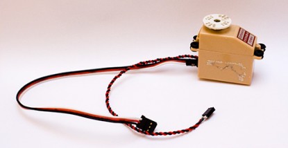
Servo feedback mod
Today I’ve modified two of my servos to allow access to the output of the variable resistor inside them. This very simple modification opens up a world of possibilities that really should come as standard on all servos. All that’s involved is opening your servo, locating the potentiometer that provides feedback on where the output shaft is and then adding an extra wire onto the center tap. After adding this wire you can read the voltage present using an A/D converter and following some simple calibration, know quite precisely what angle the output shaft is at.
The actual modification is discussed in detail over at Trossen Robotics so I won’t go into that too much.
Here’s a video of what I cooked up using the newly modified servos and an arduino board.
You can see that as I twist the horn of one servo, the other rotates to match it and mirrors the movement very closely. To do this the value from the feedback pot is read using the analogRead() function. As the output of the feedback line only reaches around 2 Volts at maximum (and goes down to around 0.2V at the other end of travel) the AREF pin of the arduino must have a voltage just above this applied to get good A/D resolution.
To scale the A/D readings I connected a simple voltage divider between GND, +5V and the AREF pin. A note here is that when I measured the maximum output from the feedback pot without the servo being connected to the arduino I measured 1.2V for one and 1.3V for the other and made my divider to output around 1.37V. However, when I connected the ground from the servos to the ground of the arduino board, the voltage seen at the outputs moved closer to 2V, which messed up my readings and meant that the A/D converter was reporting a value of 1023 (max) at about a quarter of a rotation of the servo. This was down to the fact that I was using a separate power supply for the servos which was obviously mismatched slightly from the arduino board voltage. So make sure you hook everything together before you measure the servo voltage and work out which resistors to use in your divider. Incidentally, I used values of 5.1Kohms and 4.7Kohms, worked out using this calculator.
The code I used on the arduino was largely based around the example on the Trossen Robotics page. It’s available to download below.
