PIR Sensor Mod
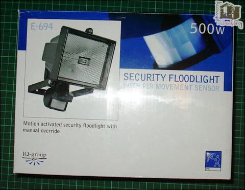
I needed a PIR sensor for a halloween project and not having a Maplin near by I decided to modify an £8.99 Security Floodlight from Argos. One thing you should note is that the default ‘switch-on’ time is around 1 minute. I didn’t need to change this for my application, but it may be an issue if you only need a short high-pulse when something is detected.
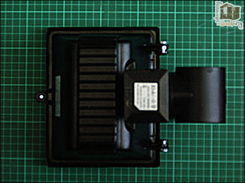
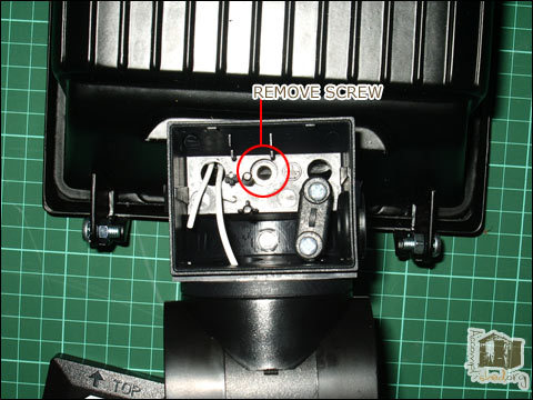
Here I’d already removed the guts. You can either cut all the wires, or do what I did and use a small screwdriver to lift the metal springs in the terminal block that are holding the wires in. After that remove the central screw as shown below to seperate the PIR section from the light.
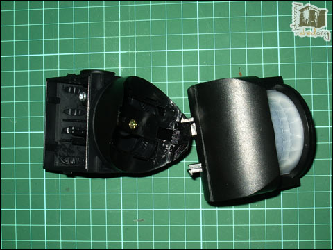
To seperate the rotating section of the PIR from the container housing the electronics just needs a good firm pull. The two sections are held together by a couple of plastic clips which should pop out easily.
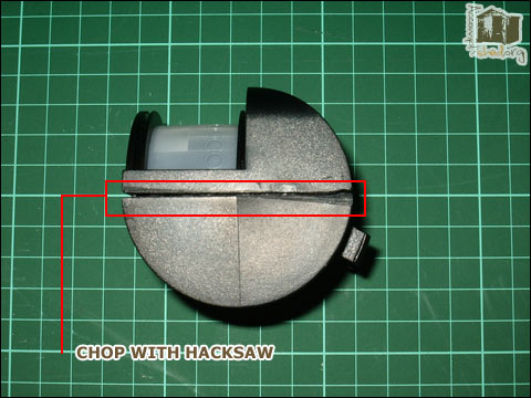
My PIR housing seemed to have glue in the seam between the two halves, so I cut a shallow channel around it until the two halves were easily seperated. The case was also held together with retaining clips as well as glue, so make sure you don’t cut through these, it’ll make putting it back together much easier.
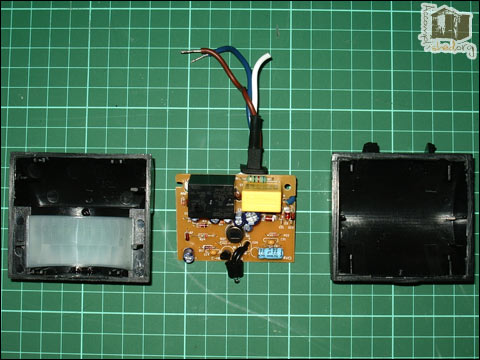
Here’s what the insides look like when you finally get the sensor housing open.
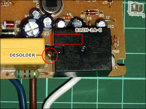
The important bit here is the relay. It’s part number is 812H-1A-C made by Song Chun. You can see the datasheet here.
What you can see from the datasheet is that the live wire is connected to one side of the relay output contacts and the white wire that goes to the halogen light is on the other side of the contact.
To allow the PIR to function as a general purpose switch we need to desolder the live wire from the relay and reconnect it so that it powers the circuit, then add another wire to the relay.
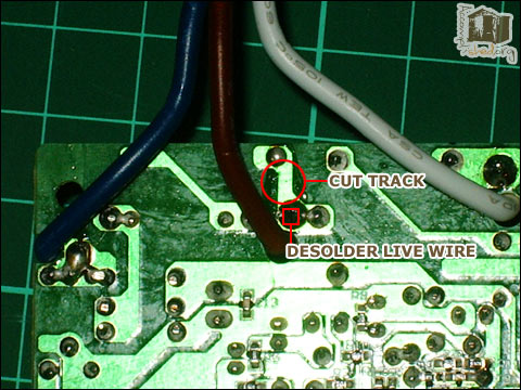
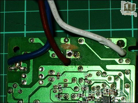
Below you can see where you should be cutting and desoldering.
And here’s the slightly messy, but effective result. Make sure you test the cut track for continuity with a multimeter, you really don’t want any mains voltages getting onto the output side of your relay.
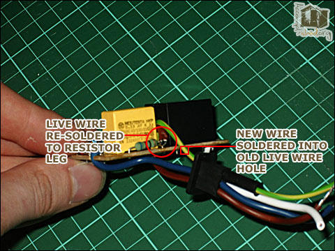
In the next shot you can just about see where I’ve resoldered the live wire onto the leg of the resistor so it can continue to power the detector circuit. I wrapped it round the leg to make the join a bit stronger. I’ve recycled some ground wire from a piece of flex and soldered that into the hole that the live wire was removed from.
After you’re done soldering, you might want to hook everything up and make sure it’s all working. I hooked up the new relay connections to a multimeter to test that it was turning on and off as it should, and also that there weren’t any stray mains voltages that could cause issues later…such as death.
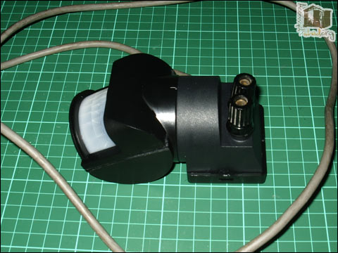
Once everything’s checked and working you can repackage it in the PIR housing. I put the original terminal block back in to hook up the mains wires and then added a couple of terminal posts through the holes on the front. These were attached to the relay wires and will now allow me to switch things on and off under control of the PIR sensor.
