Solar pendulum
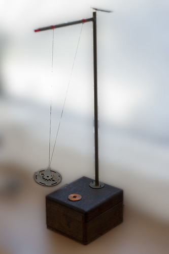
A little solar powered pendulum that I made a few years back. It uses a very simple circuit with just 2 transistors, a couple of resistors, a diode and some capacitors. Power is supplied by a two calculator solar panels wired in parallel for faster charging. The power is dumped into a coil which repels a magnet (disguised by some old brass gears) hanging from some fishing line. As the magnet swings back towards the coil the EMF generated lights a red LED in the top post and the power from the capacitors is dumped into the coil again giving the pendulum a little kick, forcing it higher.
Video, more pics and the schematic after the jump.
Pendulum swinging past the driving coil
The circuit is based on the following Solarbotics schematic that I found.
")
Here is the parts list for the circuit:
- Two 3-5V solar panels, in parallel
- 1mH coil
- 3300uF Electrolytic Capacitor
- 1000uF Electrolytic Capacitor
- 2N3904 Transistor
- 2N3906 Transistor
- Two 100kΩ Resistors
- 1N914 Diode
- Red LED
- Neodymium Magnet
- Fishing line
- Copper wire
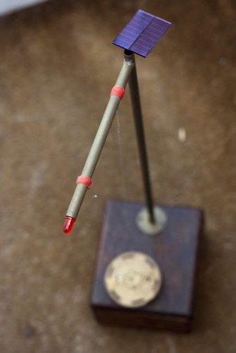
A view showing the LED and solar panels


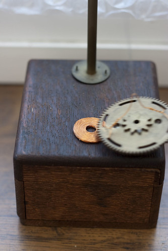
Detail view of the pendulum gears
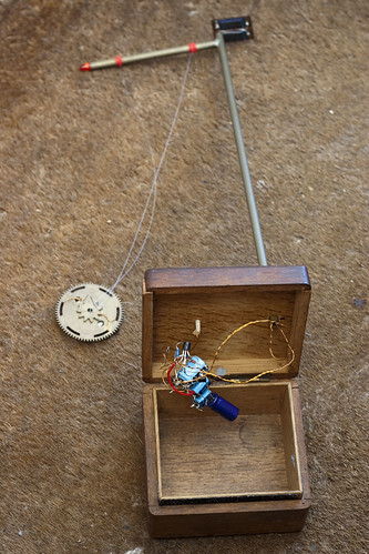
The messy guts of the thing
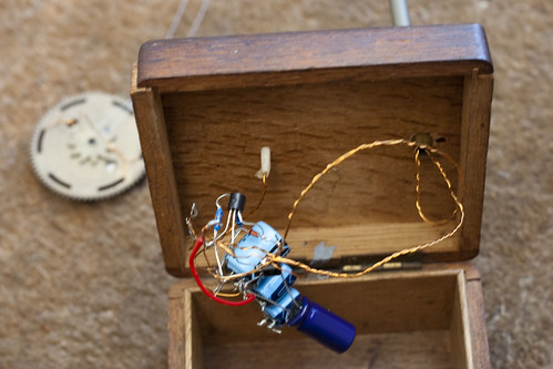
Close up of the rats nest (messy) circuit inside the box
Update – 24th June 2011: Added a parts list.
June 2nd, 2010 at 8:52 pm
Very nicely made.I like the way you used the LED in the top.
June 2nd, 2010 at 11:10 pm
[...] Accomplished via Make [...]
June 3rd, 2010 at 4:33 am
Very nice! Can you share the specs of the coil? (wire gage, turns, diameter, etc) Thanks!
June 3rd, 2010 at 9:12 am
Hi Fede,
The coil is this one from Solarbotics. I got mine from a seller on ebay though as it was cheaper (same coil but from a UK seller so the postage was less as I’m in the UK).
June 3rd, 2010 at 1:17 pm
Could you link me to the seller on eBay? (I’m from the UK so would be handy to buy it there)
Very nice build. I’ve had the book (with a project like this in it) for years but have yet to get round to making it.
June 3rd, 2010 at 1:31 pm
@unigamer
Thanks very much. I’ve just had a look on ebay for you, but it seems the seller’s no longer on there (I bought my coils quite a while ago). He was ‘eBEAMuk’, but the ebay store has gone now. I think the same seller also had ebeamuk.net but that’s also down. Looks like you might have to do a bit of hunting to track down another UK supplier…or have a go at winding your own. Sorry about that!
If you do get round to building your own version drop me a line, I’d love to see it.
June 3rd, 2010 at 7:19 pm
I was being a bit lazy anyway I suppose… I think I have the wire already from another project (coil gun – but that hasn’t been started either)
Yeah I’ll let you know when I get mine done. Prepare for the style and design to be heavily “inspired” by yours.
June 4th, 2010 at 11:26 pm
Would it be possible to make a coil with magnet wire?
June 17th, 2010 at 9:49 pm
Owen,
Saw your video of this on the “Make” site and had to try one of my own. Using wood and bamboo for the base, with a copper pendulum on a fine copper chain.
I’m having trouble getting the circuit to work. Bought the coil and magnet from solarbotics, and am trying to set it up on a breadboard before I build it for real. I’ve checked the solarbotics schematic and their “non-tech” diagram of the circuit against my setup a dozen times, including tearing it down completely and also flipping the led, diode, and caps polarities just in case I had them backward. In every case that works at all, the coil seems to be permanently energized. The magnet is drawn to center and stays there. The only time the led lights is a brief spark when I disconnect the batteries (using 2 AAA’s during testing, will use solar cells when I finish building it). That makes sense, actually: as the field in the coil collapses on shutdown, back-emf would generate a reverse pulse (like it should if it were working correctly and had stopped power to the coil).
I’m stumped. Did you have any trouble getting the circuit to work? Do you have any guesses what might make the coil permanently on?
About the coil: I bought the coil from solarbotics. I’d tried winding one myself but wanted something presentable enough to be visible on the base. The best I could come up with was pretty irregular looking and wanted to unwind into a rat’s nest as soon as I finished spooling it up. I also didn’t know enough about the circuit specs to know what kind of Henries were needed and didn’t want to re-learn the physics to figure out what that meant in terms of wire guages and radius and turns, etc.
Hope to hear from you…
Randy in Seattle
June 21st, 2010 at 9:36 am
The fact that the coil is staying on permanently suggests that the transistors might be at fault, as they should be handling the switching of the coil. I’d double check their connections and if you have spares, try using new ones in case one of them is faulty. The other thing you may want to check is the positioning of the magnet. Try to hang it so that it’s not aligned directly above the coil. It should be off to the left or right slightly, but not so much that the magnet doesn’t overlap the coil at all. Try experimenting with the vertical distance from the coil as well, as this might need to be varied depending on the strength of your magnet.
One other thing to check might be that you have no other magnetic materials around where you’re building and testing the circuit that might be causing it to trigger. Something like that is easy to overlook and can cause hours of headscratching.
Hope that helps. Let me know how you get on with it.
June 24th, 2010 at 8:11 pm
I’m thinking about building this pendulum for fun, and I’m looking at the circuit diagram.. I’m sure I could figure out what the various polarities and terminals all of these components have, but it would certainly be nice if they were labeled (especially the transistors) so I didn’t have to reason it out.
Also, what’s the mystery component with a single black bar on it? I’m not familiar with that as being a standard symbol. Is it a diode?
Thanks,
David
June 24th, 2010 at 8:21 pm
Hi David,
Sorry about the lack of labels there, that’s just laziness on my part. The mystery component is indeed a diode. Any small signal diode with a low voltage drop should do the trick.
I’ll get a properly labelled diagram up shortly and let you know when it’s done.
July 6th, 2010 at 5:49 am
I am actually having the exact same problem as Randy of the coil constantly on. However, in addition to the coil being always on, the LED is always on too. I have tried the solarbotics coil, and a homemade coil, and gone through several transistors. I do have the “mysterious diode” too.
Right now I have the circuit connected to two AAs, and when I disconnect them the LED just slowly fades.
November 12th, 2010 at 10:24 pm
I suggest that the problem of the coil’s being always on is that the transistors are incorrectly connected. The wiring diagram is not much help in that regard.
After the coil works properly: The system appears to be based on the circuit’s pulsing the electromagnet at exactly the time the pendulum goes past it — or slightly after. Therefore the circuit must oscillate at the period of the pendulum. Adjust the pendulum length to match the oscillator circuit’s timing.
June 24th, 2011 at 10:01 am
Can you add a parts list? Some of the values are difficult to read.
June 24th, 2011 at 10:26 am
Hi Kris,
I’ve updated the post with a parts list.
August 6th, 2011 at 8:05 pm
I had same problem for days scratching head, its breadboards they have potential differences in places that are not supposed to, like rows are suppose to be independant but they arent copletely got 0.6 volt difference when should be 0,,,, grrrrr
November 12th, 2011 at 8:03 pm
I saw this in the Make: magazine and decided to kill some time on a sat morning to make it. I had everything in my lab except for the coil.
I tried a voice coil from a hard-disk read arm–did not work. Found some other coils in my tons of harvested components…no luck.
I have tons of magnet wire of varying gauges, but the challenge of winding a decent coil seemed daunting.
Then I came up with a brilliant idea. I took an axle from my pile of Lego technics parts (I probably have about $10,000 invested in Lego parts…LOL). Then I took two of the thin Lego wheels and placed them on the axle separated by about a quarter inch or so. I attached the axle to my drill motor and wound the wire on to the axle…continuously moving the wire back and forth to get a nice coil. I left the wheels and axle intact and wired p the circuit…Bingo!
January 4th, 2012 at 9:07 pm
Hello Owen, saw your pendulum article in MAKE. I had an idea for a line array of pendulums, where each “tickles” the one next to it, kind of like a series of dominoes. Also, if you can, check out the now defunct English magazine called “Everyday Practical Electronics”, I think they might still sell CD-Rom copies of issues. They stopped publishing around 2002. They had lots of nice articles on solar powered led flashlights, pendulum circuits and lots of PIC projects. Hope that helps. EMAIL me for more discussion if you like. – RICK
January 4th, 2012 at 10:06 pm
Hi Rick, thanks very much for your comment, the array of pendulums is a really nice idea. I might have to have a tinker and see if I can get something like it working. I’ll have a look into the magazine you mentioned too, it sounds interesting.
March 14th, 2012 at 7:00 pm
Will your circuit oscillate without the pendulum ?
Looks like the series combination for 1mh and 1000uf will oscillate around 159 Hz. I think the frequency has to be near the frequency of the pendulum or at least a multiple of that frequency.
May 21st, 2012 at 9:54 am
hey guys,
 and I get continuous drop of 1.6V across the coil. my 3904 transistor remain cool but 3906 gets heated while operation.
well i am new to electronics. Well, I just wanted to ask: do you really think this circuit has to do anything with the frequency like davad says just above my comment. I guessed the swinging of pendulum triggered the circuit to provide the magnetic nudge and its independent of whatever is the frequency of your circuit or your pendulum.
I am using homemade coil. I made a big one. wire used was 26 gauge
The coil is able to produce over 1000uT of magnetic field at 4V. I measured using my android phone.
I am using 4V supply. My LED doesn’t flash. I guess, it has burnt down
can anybody help?
November 19th, 2012 at 6:44 am
Am I the only person on the planet that cannot get this thing to work? Tried this ‘schematic.’ No. Bought the ‘kit’ from techkits.com. No. Wired up the non-solar one at trainelectronics.com/Pendulum/article.htm to my own layout. No. Wired up the ‘train’ version exactly (including the all-important insulation colour) as laid out on his breadboard. No. Tried two different coils. Tried two different magnets.
Twenty-odd hours into two circuits ‘described as fun’ and I’ll be damned if I can get one to oscillate; the magnet ALWAYS locks up
Anyone, anywhere, any ideas?
urbanwriter at g mail
December 3rd, 2012 at 12:35 am
Just a few comments, associated with the solar pendulum I built using the coil I purchase from solarbotics. i built the circuit using the listed parts. I initially used a dc power supply to get it to work. The power supply was set to 3 vdc, the pendulum immediately was attracted to the coil. The led came on and did not go out. The power supply was drawing over 0.5 amp of current. I reduced the power supply to 1.3 vdc, current dropped to 11 ma, and the pendulum started to swing normally. I checked the waveform using an oscilloscope at the coil, while the pendulum was was not put in motion, the scope showed a pulse 20v peak to peak going negative from zero, at a frequency of approx. 10kc. The led was not able to flash at a 10kc rate instead it appeared to be on all the time The unit worked with no trouble when I used the solar cell instead of the dc power supply. The led flashing indicates it is responding to the emf of the coil, this can also occur if the circuit is oscillating on it’s own without reacting to the pendulum swinging. I believe my initial problem, was due to the use of a power supply, instead of using the solar cell. At the moment it is working fine using the solar cell. Hope, my experience with this project will be of some benefit to another builder.
December 29th, 2012 at 10:30 pm
hey i built this and i have a few problems when i turn it on the coil either atracts the magnet or repels it depending on which way i have the magnet and it eventualy stops plus when i turn it on it taks a few seconds for the led to turn on and when it does it stays on so i was wondering if anyone know what might be wrong with it.
christian,
December 29th, 2012 at 11:04 pm
i have another question is there a spicific led i need or can a use a recular one and just swith it in the oposite dircetion
January 2nd, 2013 at 5:10 pm
The circuit really needs to work from a relatively high impedance power source like 1.2-ish volts from solar cells. because the voltage on 3300uF cap must reduce with each drive pulse to less than ~0.8V so the 3904/6 both turn off. An alternative would be to use a single cell or 1.2V power supply source and put a resistor like maybe 100 ohms in series with it.. if it still locks up, use a larger resistor.
January 4th, 2013 at 7:58 pm
hello ive been trying to build thid on my spare time and i cant get it to work ive tryed all diffrent ways i can think of on my breadboard if anyone has one, can they take a pic of how they set it up on their bread board and send it to me at hockeedude@hotmail.com, thanks
June 12th, 2014 at 2:35 am
Hi, I am also one of the people who cant get this circuit to work. I have my transistors wired exactly how they are shown in the circuit yet my coil automatically energizes when plugged into a 3 volt battery. The LED automatically turns on when power is on and coil will either repel the magnet to one side or attract it. I dont know what else to try.
October 25th, 2014 at 6:56 am
This circuit was described in Junkbots, Bugbots and Bots on Wheels published by Mcgraw Hill/Osborne. If you are using a 3 volt battery then you must insert a resistor in series with the battery. The authors suggest 5K to 10 K ohm. Try using 10K pot and when you get it running you can either leave the pot in place or substitute a fixed resistor. If the led appears to be permanently on then the circuit is probably oscillating, but the frequency is too high for the eye to see. Usually because of the missing resistor. 30 Gauge magnet wire wound on a plastic sewing machine bobbin works great for the coil. Wind on enough to fill the bobbin. I’ve build a few solar/battery pendulums using this and other circuits. Once you insert the resistor the rest of the circuit isn’t too picky, it will work.